
A PM2.5 sensor is also called a dust sensor, which can be used to detect the dust concentration in the air around us, that is, the value of PM2.5. Dust with a diameter of less than 10μm that can enter the alveolar region is also commonly referred to as respirable dust in Aerodynamics. Most of the dust particles with a diameter of more than 10μm are deposited by impact, and most of them are deposited in the nasopharynx when inhaled by the human body, while the dust below 10μm can enter the deep part of the respiratory tract. Most of the dust deposited in the alveoli is below 2.5μm. The PM2.5 dust sensors currently on the market have the following principles:
(1) Light scattering methods
At present, the measurement of atmospheric particulate matter in China mainly adopts the gravimetric method. The principle is that the sampler extracts a quantitative volume of air at a constant speed, so that PM2.5 and PM10 particles in the ambient air are filtered on a filter membrane of known mass. According to the quality of the filter membrane before and after sampling and the volume of the sampled gas, the concentrations of PM2.5 and PM10 were calculated.
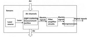
Figure 1 The schematic diagram of the light scattering dust sensor
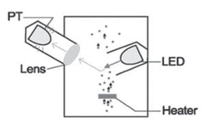
Figure 2 The schematic diagram of the light scattering dust sensor
(3) Micro oscillating balance methods
The micro-oscillating balance method is a mass sensor with an oscillating hollow conical tube inside. The oscillation frequency of this oscillating tube depends on the characteristics and quality of the conical tube. When the sample gas enters the sensor and passes through the filter, particulate matter will deposit on the filter, and the change in the quality of the filter will cause the oscillation frequency of the filter to change. We can calculate the mass of the particles deposited on the filter membrane through the change of the oscillation frequency to calculate the mass concentration of the particles in the gas.
4) Beta ray methods or β ray methods
The Beta ray method uses the principle of Beta ray attenuation. The ambient air is sucked into the sampling tube by the sampling pump. After the gas passes through the filter membrane, the particulate matter will be deposited on the filter membrane. At this time, the deposited particles are irradiated with beta rays, and the energy of the beta rays will be attenuated. We can calculate the particle’s concentration from the attenuation of the beta rays.
Because principles 2, 3, and 4 are difficult to apply and the price is high, the dust sensors used in air purifiers at this stage are light scattering sensors.
As shown in Figures 3 to 6, most dust sensors contain metal housing. This metal shell is used for grounding, and the purpose of grounding is to shield external interference. If there is no grounding metal for shielding, the external interference will affect the current signal generated by the sensor, thereby affecting the accuracy of the displayed data.
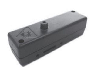
Figure 3 Alphasense PM2.5 sensors or dust sensors
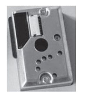
Figure 4 Japanese Sharp Dust Sensors
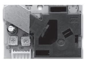
Figure 5 Japanese Shinei dust sensors
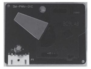
Figure 6 Korean syhitech dust sensors
For those sensors without a metal shell on the outer surface, there is also a shielding cover composed of grounded powder metal particles, which can also play a role in shielding external interference.
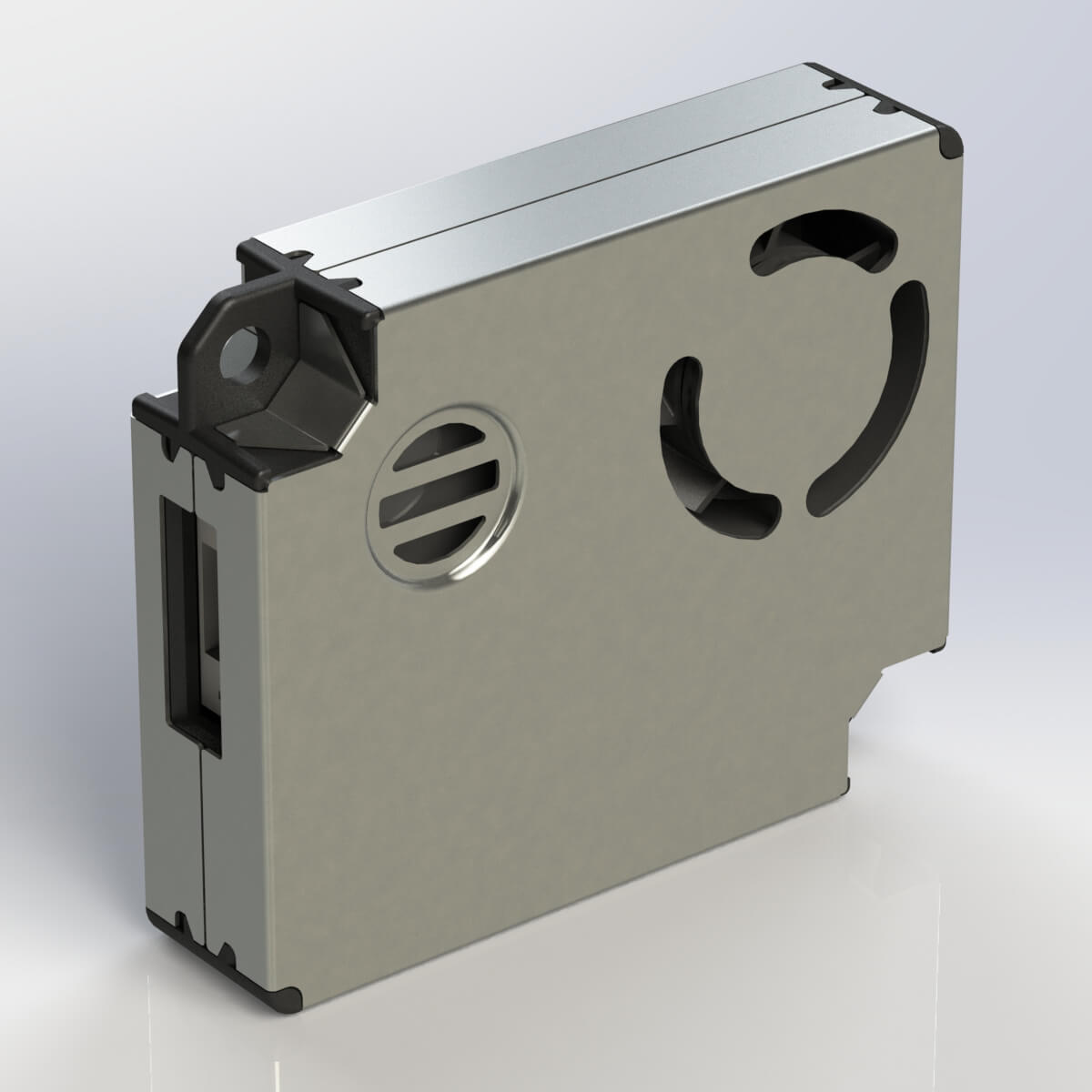
Therefore, we can see that the dust sensors using the laser scattering method all contain similar metal shielded housings with grounding. The dust sensor of the tested prototype also has a similar structure (Figures 7 and 8).
Figure 7 The front of the dust sensor of the tested prototype
Figure 8 The front of the dust sensor of the tested prototype
Through the multimeter, it is known that the pin indicated by the arrow in Figure 8 is connected to the metal casing, that is, the pin is the ground pin input. Re-examine the creepage distance and electrical clearance between the ground pin and other live parts. See Figure 9. As can be seen from Figure 9, the electrical clearance between the ground pin and other live parts is less than 1 mm, and there is no isolation. The dust sensor operates at less than 24V, which is a safe extra-low voltage (SELV).
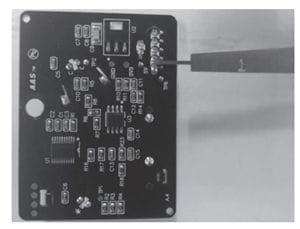
Figure 9